The pull test tells you what the ground can offer. The load calculation tells you what the structure needs. These two numbers have to be compared before you can confirm the anchorage is adequate — not after, and not by assumption.
Every marquee, tent, and temporary structure applies a force at each anchor point. That force has to be resisted by the stake — specifically by the friction and bearing resistance between the stake shaft and the surrounding ground. If the stake cannot provide that resistance, it will pull out. Understanding what force each anchor point needs to resist is the starting point for the whole anchorage decision.
This guide covers the practical side of that calculation for UK marquee hire companies and event professionals: where anchor loads come from, typical load ranges by structure type, how pull test results translate into anchorage specification, and the threshold at which you need a structural engineer involved.
Where Anchor Loads Come From
Anchor loads on marquees are driven primarily by wind. Dead loads — the weight of canvas, poles, and fittings — are largely taken by the structure itself. What the ground anchor has to resist is the force that wind applies to the structure, transmitted through the guy ropes or baseplate connections down to the stake.
Wind applies a horizontal force across the structure's projected face area. That horizontal force resolves into tension in the guy ropes, and the angle of the guy rope determines how much of that tension the stake has to resist vertically. A rope set at a shallow angle (say 30° from horizontal) amplifies the anchor load — the more nearly horizontal the rope, the higher the pull-out force required at the stake.
Three variables govern the anchor load at any given point:
- Wind speed and exposure — UK design wind speeds vary by location and site exposure. Sheltered valley sites face lower pressures than open hill or coastal sites. The same structure can require different anchorage on different sites.
- Structure type and span — different structures distribute load to anchor points differently. A clearspan frame applies near-vertical load through its baseplates. A pole tent concentrates load at the ridge and eaves guy positions. A stretch tent distributes load across all peg positions at the tent perimeter.
- Guy rope geometry — the angle of the guy rope relative to horizontal. A 45° rope requires the stake to resist a pull-out force equal to the horizontal component. A 30° rope requires the stake to resist more.
Full calculation requires structural engineering input for anything approaching the limits of the structure or unusual site exposure. For typical hire company work on known sites, the guidance below provides working reference ranges.
Typical Anchor Load Ranges by Structure Type
The figures below are working reference ranges for standard UK event conditions — moderate wind exposure, typical UK design wind speed, structures within their rated span. They are not engineering specifications. Unusual site exposure, large spans, or structures at the upper end of their rated capacity require formal structural assessment.
| Structure type | Position | Typical range | Notes |
|---|---|---|---|
| Sailcloth / pole tent | Ridge guy positions | 8 – 20 kN | Highest loads on site; primary storm anchoring positions |
| Sailcloth / pole tent | Perimeter eaves guys | 3 – 8 kN | Lower load but consistent around perimeter; larger tent = higher per-position load |
| Clearspan frame | Baseplate anchors | 10 – 35 kN+ | Subject to racking forces; large spans or high exposure require SE specification |
| Stretch tent | All perimeter pegs | 3 – 10 kN | Sustained tension across all anchor points; corner and high-point positions typically highest |
| Traditional pole marquee | Ridge poles | 6 – 15 kN | Load concentrated at ridge pole positions; dependent on span |
| Traditional pole marquee | Side wall guys | 2 – 6 kN | Perimeter positions; lower than ridge but significant across full length |
| Tipi | Perimeter pegs | 3 – 7 kN | Relatively even distribution; larger tipis toward upper end of range |
| Big top / round tent | Main guy positions | 15 – 40 kN+ | Always requires structural engineer specification; multiple stakes per anchor point standard |
| Inflatable structure | All anchor points | 2 – 8 kN | Governed by EN14960; engineer or supplier specification required |
A 20 kN anchor point needs a stake that can provide 20 kN of pull-out resistance — at the required working depth, in the actual ground conditions on the day. If your pull test on a sample stake at working depth gives 35 kN, and you apply a 2× safety factor, your available working resistance is 17.5 kN. That is below 20 kN. The anchorage arrangement needs to be reviewed — gang staking, deeper driving, or a larger stake.
Turning a Pull Test Result Into a Working Load
A pull test gives you the peak load at which a specific stake, driven to a specific depth, in specific ground conditions, begins to displace. That figure is the ultimate pull-out resistance for that stake in those conditions. It is not the working load you can rely on.
A safety factor is applied to account for variability in ground conditions across the site, variation in stake driving depth between crew members, dynamic loading from wind gusts rather than steady-state load, and the consequences of anchor failure for the structure and the people inside it.
Typical safety factors for temporary structures
| General guidance (MUTA / IFAI) | 2× the calculated working load |
| Occupied structures, public events | 2.5× to 3× |
| Structural engineer specification | Per engineer's report — often 2× with additional checks |
| EN14960 inflatable anchors | Per standard — typically 1.5× with dynamic load allowance |
The practical rule for most UK hire company work: your pull test result, divided by 2, is the available working resistance for that anchor arrangement. That figure must be at least equal to the load your structure applies at that anchor point.
Worked example
Situation: 15m sailcloth tent, standard UK exposure. Ridge guy positions require 14 kN working resistance (from structure specification). Ground: firm loam.
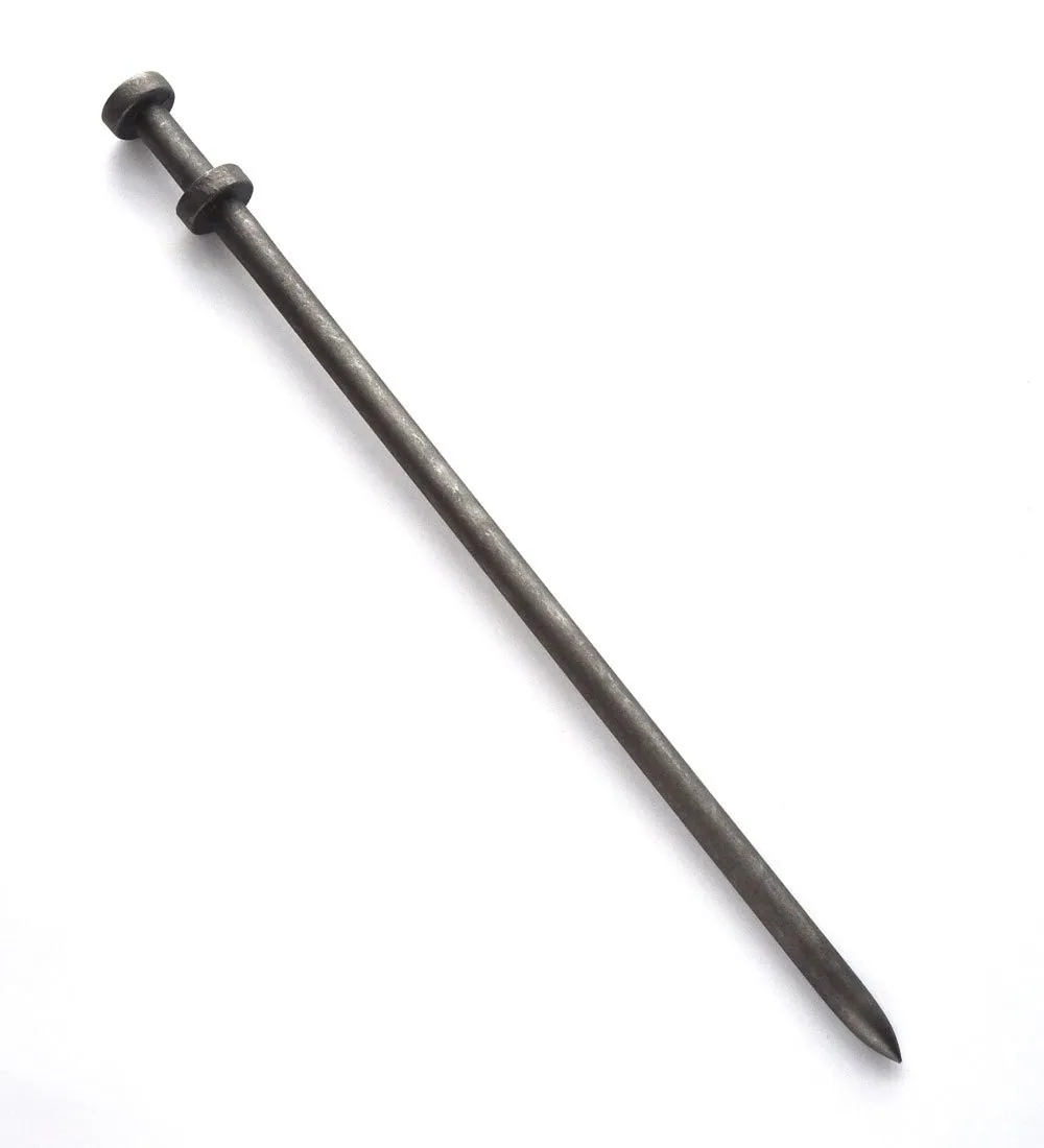
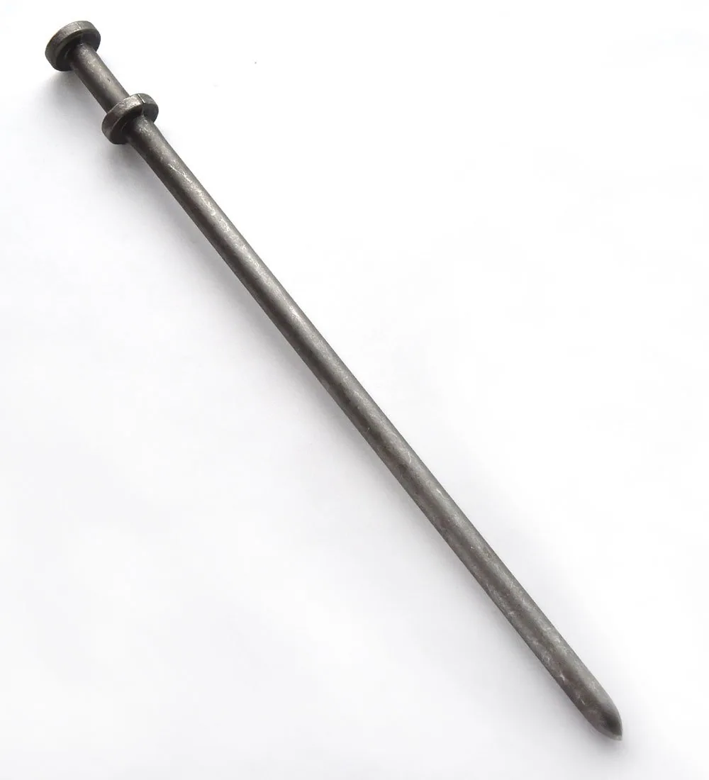
Pull test: Drive a 42" Tiger Stake to full depth at a representative ridge position. Pull test result: 28 kN peak displacement load.
Available working resistance: 28 kN ÷ 2 = 14 kN.
Conclusion: A single 42" stake at this depth, in this ground, meets the requirement with a 2× safety factor. If the pull test had returned 22 kN, available working resistance would be 11 kN — short of the 14 kN required. The options: drive a 48" or 60" stake to get more depth, install a gang stake arrangement at that position, or reclassify the position with the structural engineer.
Pull testing a sample stake is most useful when done before committing to an anchorage arrangement — not as a retrospective check. If you know you need 14 kN and the sample test returns 22 kN, you can decide to drive deeper or add stakes before the whole installation is driven.
Why Clearspan Baseplates Are Different
Clearspan frame structures — aluminium frame marquees — transmit anchor loads through their leg baseplates rather than through guy ropes. The loads at these positions are substantially different from a traditional marquee.
Instead of a tension force pulling the stake upward at an angle, the baseplate applies a combination of vertical uplift (from wind on the roof) and a horizontal racking force (from the frame trying to lean in the wind). The anchor arrangement through the baseplate — typically two or three stakes per leg — has to resist both components simultaneously.
At large spans (15m+) or in exposed conditions, baseplate anchor loads can be very high. A 20m clearspan in exposed conditions, with anchors driven through ratchet plates in hard ground, is not the same problem as a 10m clearspan in a sheltered garden. The structure manufacturer or your structural engineer should provide anchor specifications for the structure size and site exposure you are working with.
The 42" or 48" Tiger Stake through a ratchet plate is the standard arrangement for clearspan baseplates in normal UK conditions. For larger spans or exposed sites, get the anchor specification from the manufacturer — then use pull test data to confirm the ground can meet it.
When to Involve a Structural Engineer
Most UK hire company work falls within published reference ranges and can be managed with good practice, appropriate stake selection, and pull testing. Some situations require formal structural engineering input.
Typically requires SE input
- Large clearspan structures (20m+ span)
- Big top or round tent anchoring
- Exposed coastal or hilltop sites
- Events requiring local authority licence
- Insurance specifications that require engineer sign-off
- Unusual ground conditions (made ground, shallow bedrock, high water table)
- Structures at the upper end of their rated capacity
- Structures you are unfamiliar with
Usually manageable in-house
- Standard sailcloth and pole tents at known spans
- Stretch tents in sheltered or moderate exposure
- Tipis and bell tents in normal conditions
- Clearspan up to 12–15m in moderate exposure
- Sites you work regularly with known ground
- Structures within manufacturer published specifications
If you are in any doubt about whether a site or structure falls within the manageable range, the cost of an engineer's report is small relative to the cost of a structure failure. MUTA members can access guidance through the association. Your structure manufacturer should be able to provide anchor specifications or direct you to a qualified engineer.
The Practical Workflow
The full sequence for verifying a ground anchor arrangement:
-
1
Know your required load From structure specification, manufacturer's anchor guide, or structural engineer report. If none of these exist, use the reference ranges in this guide as a starting point — but recognise they are reference figures, not engineering specifications.
-
2
Drive a sample stake at a representative location Drive to the working depth you intend to use on the installation. Choose a representative ground location — not the softest or hardest spot. The test result only applies to ground conditions similar to the test point.
-
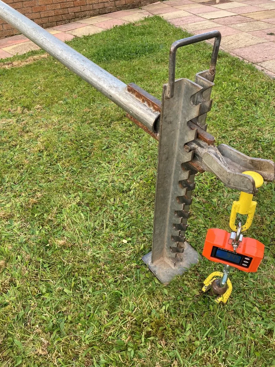
3
Pull test and record the result Apply load in the direction the structure will apply it — typically at or close to the guy rope angle. Record the peak displacement load in kN or kg. See the pull test guide for method and equipment.
-
4
Apply the safety factor Divide the pull test result by your safety factor (typically 2× for occupied temporary structures). The result is your available working resistance per stake.
-
5
Compare against required load — and decide If available working resistance ≥ required load: single stake is adequate for that position. If below: options are a deeper stake, a larger diameter stake, or a gang stake arrangement. For gang staking, available working resistance is the sum of all stake capacities in the arrangement.
-
6
Record and retain Record the pull test result, the ground conditions, the stake used, the driving depth, the safety factor applied, and the comparison against required load. For licensed events and insured structures, this documentation supports sign-off and demonstrates due diligence.
How Stake Quality Affects the Calculation
Pull-out resistance comes primarily from two sources: friction between the stake shaft and the surrounding soil, and bearing resistance against the soil at the stake tip and along the shaft. A stake that has reached full working depth, driven straight, provides more of both than a stake that has been steered off-axis, or that has bent during driving and seated less than true.
High alloy steel stakes maintain their geometry under the driving loads typical of compacted or stony ground. A mild steel stake that bends at the tip during driving has reduced effective depth — the bent section does not contribute pull-out resistance in the same way as a straight shaft. The result is lower actual pull-out resistance than you would expect for the nominal driving depth.
This matters for load calculation because the calculation assumes the stake is at working depth and seated correctly. A bent or partially-seated stake delivers less resistance than the pull test on a correctly driven stake would suggest. Maintaining stake quality through a season — choosing stakes that stay straight, and replacing any that have taken permanent deformation — keeps your pull test data representative of what your stakes are actually delivering in the ground.
Common Questions
What is the minimum pull-out resistance for a marquee stake?
There is no single universal minimum — the required pull-out resistance depends on the load at each anchor point, which varies by structure type, dimensions, and design wind speed. The MUTA Best Practice Guide sets a recommended minimum figure for standard UK installations. For clearspan structures and larger marquees, a structural engineer's specification will typically set higher requirements based on load calculations.
How do I work out the load at each anchor point?
The starting point is the structure manufacturer's specification or an engineer's load schedule. For guy-rope structures, the load per anchor depends on the guy tension and its angle. For clearspan marquees, baseplate loads are calculated from the overall racking forces on the frame. Once you have the load figure, apply a safety factor — typically 2× the working load — to arrive at the required pull-out resistance.
Does stake material affect pull-out resistance?
Yes, indirectly. Pull-out resistance is primarily determined by the stake's contact area with the soil — length and diameter — and by ground conditions. However, a stake that bends during driving does not reach full working depth, and a bent shaft does not contribute resistance in the same way as a straight one. High alloy steel stakes that maintain their geometry across repeated driving deliver more consistent pull-out results than mild steel stakes that deform.
When do I need a structural engineer for marquee anchoring?
For standard hire company setups at established venues in typical UK conditions, a structural engineer is not always required — the structure manufacturer's specification and MUTA guidance often suffice. An engineer is advisable when working at elevated sites with high wind exposure, installing large or complex structures, working to an event safety management plan, or when a client's risk assessment or insurance requires it.
Products referenced in this guide

Working out your anchor loads?
Size the arrangement with the stake calculator, then spreader bars and Tiger stakes to hit the number. We're happy to sense-check it.